Polygon type ball mill is an important piece of grinding equipment after the crushing process, and it can be used for drying and wet grinding of nearly all kinds of ores and other grindable materials. Typically, this product is found in ore beneficiation process and aerated concrete plant.
Our ball mill is mainly composed of feeding section, dischargingsection, rotating section, driving section (reducer, pinion, motor, electriccontrol), etc.

schematic diagram of polygon type ball mill
This machine is a skeleton pattern ball mill with horizontal cylindrical turning gear, drive by outer gear and two hoppers. The material goes to the first hopper after the spiraling by the quill shaft from the feeding equipment. The hopper has ladder sheathing or corrugated sheathing with steel balls inside, which will fall under the effect of centrifugal force by barrel turning to ram hard and grind material. After the kibbling in the first hopper, by monolayer partition panel, the material will enter the second hopper, which has plane scale board with steel ball inside to grind material. The powder material will be discharged from the grid plate to finish the grinding.


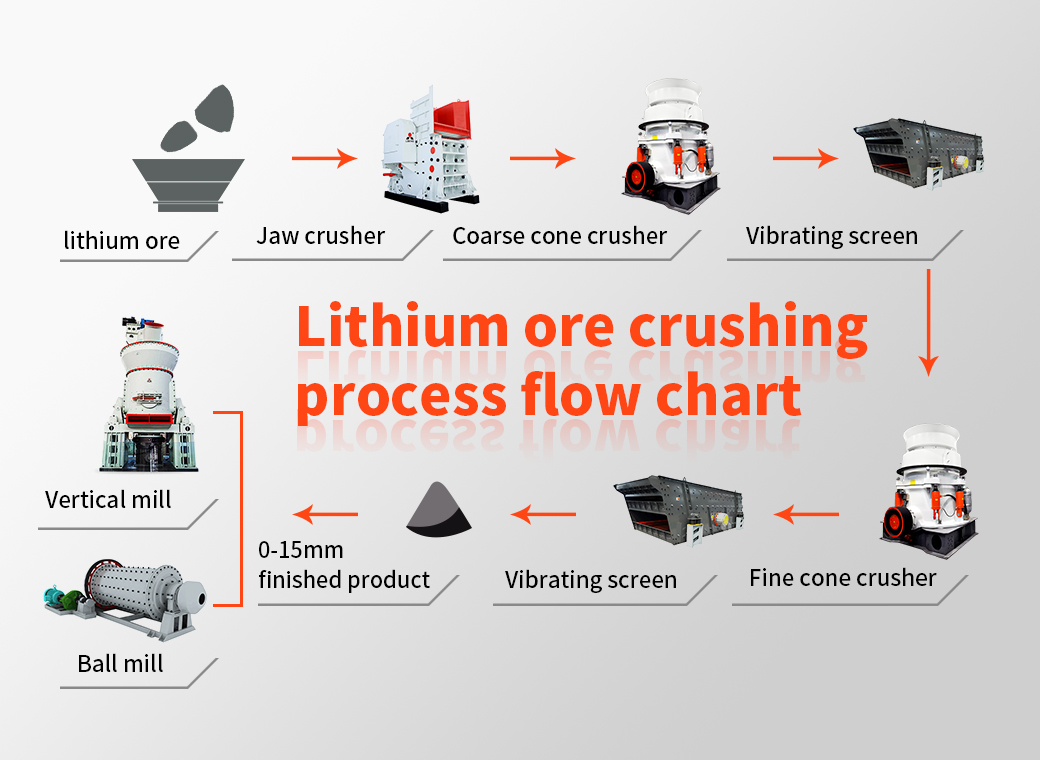
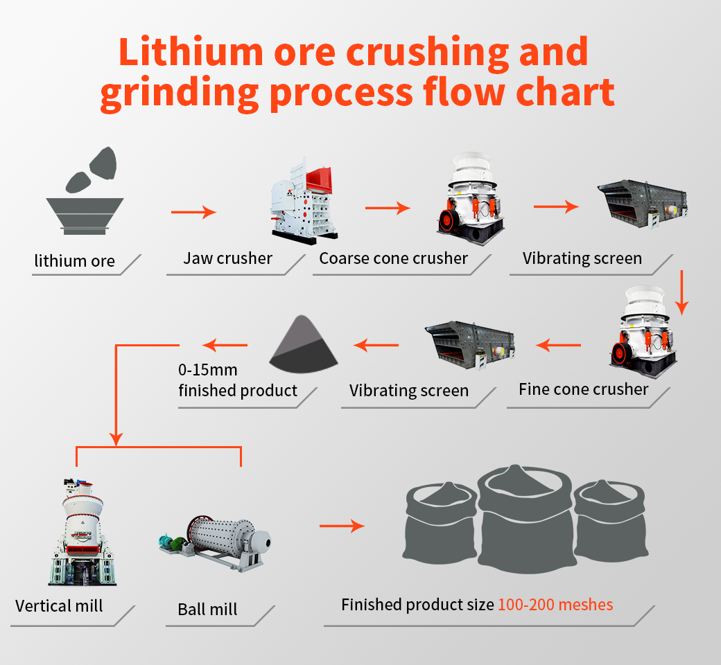 Spodumene: According to the hard rock crushing process, the crushed product is generally 5-40mm, combined with different design requirements of customers, two-end or three-stage crushing, high-grade crushed products (above 4-5%) can be directly used in the metallurgical process to produce lithium carbonate Or lithium hydroxide, the particle size of the finished product is generally around 20-40mm; low-grade generally requires ball mill grinding and separation, and the particle size of the finished product is generally around 5-20mm;